|
|||
|
Filter Select+Plus, Web Edition™ is designed to guide the user through the selection process of Smiths Interconnect's Standard Bandpass Filters. Upon entering filter specifications, the application will display a specification sheet which includes electrical performance data and a mechanical outline. From the specification sheet, links will lead to the interactive electrical plot, a download of the filter documentation in Adobe PDF format and addition of the filter to the RFQ queue for quotation. Once all the filters have been examined and added to the queue, a link to the quotation request form may be followed allowing the user to generate an RFQ electronically. Currently available filter topologies are Ceramic Filters, Discrete Filters, Cavity Filters, and Waveguide Filters. For other types of filters and custom filters please contact Smiths Interconnect. Specification Input Section: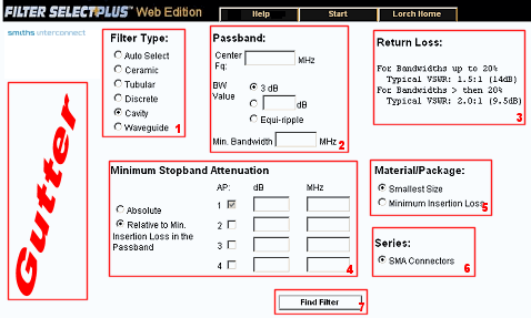 This section is where the filter specifications, filter type and style are entered. The first decision that must be made is which filter type will be used for the filter solution. 1 - Filter Type:There are four filter types and an Auto-select option. Auto-select will find all the filters that are solutions with a maximum of one filter from each of the filter types. These will then be presented in a table listing the part number, the projected insertion loss and the filter type. When manually selecting the filter type, more choices for package types and filter goal (minimum size or minimum insertion loss) become available. When using Auto-select, the default package type for the filter type and use the goal of minimum filter size will be chosen by the program. 2 - PassBand:The passband information must be entered next. This includes the center frequency of the filter, the bandwidth type (3dB, user enterable dB value of at least 0.5 or an equi-ripple) and the minimum acceptable bandwidth 3 - Insertion Loss/Return Loss:Next, if using the Auto-select option the maximum acceptable insertion loss must be entered. This enables the software to find a filter that will meet this criterion while still trying for the goal of minimum size with in a filter type. The return loss specification for the filter type will be displayed. 4 - Minimum Stopband Attenuation:Additionally, the stopband attenuation(s) must be entered. These can be either an absolute stop band or one relative to the minimum insertion loss in the passband. A minimum of one attenuation point is required and up to four can be entered. 5 - Material/Package (Goal):Next, if manually choosing the filter type, the filter goal must be chosen in the form of the material/package of either smallest size or minimum insertion loss. 6 - Series:Filter types will have at least one series but may have more. These are usually related to how the filter is connected to the circuit and will not normally adversely affect the filter's performance. 7 - Find Filter Command:Finally, by pressing the "Find Filter" button, the application will find the filter(s) and display the specification sheet or a table of possible solutions for the user to select which solution to view in specification sheet format. Gutter: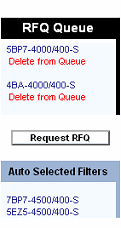
This is where the dynamic links are placed such as the RFQ Queue and the Auto Select found filters. By following the link of any filter it will lead to the filter's specification sheet. The RFQ Queue consist of the filter's part number as a link to its specification sheet and a link below this titled "Delete from Queue" for removing the filter from the queue. There is also a link button "Request RFQ" that leads the RFQ form. The "Auto Selected Filters" area contains all of the filters that the Auto Select found. These filters remain here for easy navigation between them for comparison of their results. |